Welcome to RVForums.com

  • Register now and join the discussion
  • Friendliest RV Community on the web
  • Modern site for PC's, Phones, Tablets - no 3rd party apps required
  • Ask questions, help others, review campgrounds
  • Get the most out of the RV Lifestyle
  • Invite everyone to RVForums.com and let's have fun
  • Commercial/Vendors welcome

Battery Help!

Welcome to RVForums.com

  • Register now and join the discussion
  • Modern secure site, no 3rd party apps required
  • Invite your friends and let's have fun
  • Commercial/Vendors welcome
  • Friendliest RV community on the web

DHudson

RVF Supporter
Joined
Dec 11, 2020
Messages
391
Location
Texas
RV Year
2000
RV Make
Newmar
RV Model
Dutch Star 3858
RV Length
38 ft
TOW/TOAD
None
Fulltimer
No
Let me start by saying I am a ASE Master Tech and a GM Master Tech.
Just stating this so you will know that I know about vehicles and terms.
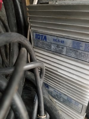
Inverters and Converters are new to me though.

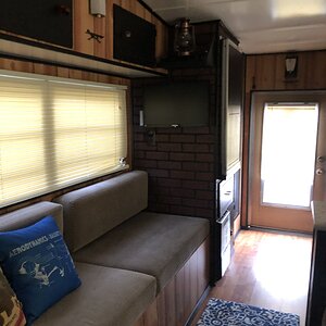
So, I just bought this 2000 Dutch Star, Cat Engine, Freightliner Chassis.
The place I bought it from, had 2 marine batteries in it.. Everything hooked to those 2 batteries, hooked in parallel. That's all. I knew this when I bought it.
So I got 2 group 31 batteries for starting batteries and 4 2GC Golf cart batteries for the house.

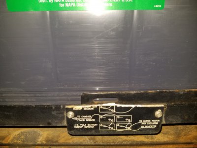
I need to know for sure which wires go where between the starting batteries and the house batteries.
I hooked them up like I thought they should go and started checking voltage on both sets with engine off and running,
and generator off and running. I am do seeing any voltage difference between engines running or not,
With the generator running, the HW-RV 50 Surge Guard "over/under voltage" light was flashing.
I heard a pop and pretty sure it was a breaker.

I shut off the generator and disconnected power from the house batteries.

I shut off the engine, and tried to restart it. It started, but, ( and it may just be coincidence) the started stayed engaged . Has not done this until now.
Did not disengage when I cut the key off.
Disconnected power from the starting batteries..Touched the wires back to the terminals (starting batteries) and the starter did not re-engage.

I made sure every thing was disconnected and stopped

I believe wires are not hooked up right, but can find no information on what wire goes where.

There are 2 groups of wires that come into the battery box area, and I can not decide if each group should all be together or mixed between battery sets.

ANY HELP would be appreciated.

Thanks in advance
Danny
 
Danny,

It would be very presumptuous of me to say anything about a 2000 Dutch Star, as I only have experience with the 2016 Ventana. You might compare To help decipher...but a true 2000 year model vet on the same chassis is likely to be able to better steer you.

My coach did have labels affixed...at both locations with the wiring diagram...this is a help if that is/was placed on your coach. I also have an account thru DTNA as an owner/operator...which gives me access to ez-wiring for my chassis alone. The Freightliner wiring is detailed there. Newmar has comnet...and you can search for information, but to my knowledge...they don’t have an easy reference library for detailed schematics. Some of their customer service reps have better ways to get this and may be able to email files to you.

I would check thoroughly to make sure the 12v group 31 batteries were paralleled. And the 6v GC2 batteries were connected series as pairs...and the pairs paralleled. Having 24v going to the starter could be bad.

On my coach, the group 31s are both grounded to the frame. There is a disconnect switch which cuts the feed from the chassis batteries to the front dash area. The end of the two distribution leads terminate in the basement compartment under the drivers seat. These are fused back in a module in the chassis battery compartment. The other wires you may see go to the starter, alternator, there is a bi-directional cable, and a small solar charge lead...going to a 5 - 10w panel in the roof.
The bi-directional relay wire goes to some form of relay which allows the house system and chassis system to share their respective charge system with the other when the programmed parameters are met...or you press a BOOST switch on the dash to bootstrap the two banks manually.

As you find components...good to snap a photo with a phone. Then most of this stuff is available for download thru the manufacturers website. Very helpful as far as installation diagrams, normal function, and troubleshooting steps.

The house bank is enough to make you go cross eyed on our coach. There are four pairs running as 12v...made by series connection via copper bars between a pair of batteries. Our Inverter is connected to one pair, the House DC electrical is connected to a second pair, the bi-directional wiring goes to a third pair...and a fourth pair is there just to tag along. All four pairs have additional jumpers to parallel them to one another.

If you take pictures of stuff...posting those will give those trying to figure out what’s happening with your rig a better shot at seeing if they can sort out what may be going on.

I hope the Starter isn’t beyond help.

I sure hope someone with your same model coach is watching...and can maybe send photos of how things are wired and working.
 
20201203_091200.jpg


Typical decals stuck in compartment near batteries...
20201202_092447.jpg
 
"I would check thoroughly to make sure the 12v group 31 batteries were paralleled. And the 6v GC2 batteries were connected series as pairs...and the pairs paralleled. Having 24v going to the starter could be bad."


31's are in parallel - 12v.
6v Gc2 are in serial 2 &2 Parallel - 12v.

I have my starter and alternator to the 31 batteries ..Starts and runs now. Ran out of day light, so will check tomorrow if they are charging...Alt. could be bad.. Will check output at alt. tomorrow.

Now on to the house batteries..

They are REALLY foreign to me..Guess I will learn something new.....I Hope.

Thank you for the input.
 
Typical of Freightliner Wiring diagram of Chassis.
342E03F8-A3BA-4B6C-A77E-ED0FD248936F.jpeg


Good to hear it’s running. That’s always a more positive place to be.

I don’t know if you’ve scoured the “Black Bag” Newmar is famous for including with each coach. I found a handout of about six pages in total. It basically blueprints the locations where 12v systems have fuse panels and self-resetting breakers. If You have one, it is a big help in finding these hidden components...and where to go look when a particular item is not being powered. My coach is “all-electric” ...so no propane appliances. I can‘t help much as I’m not sure what Inverter you have, if it is wired to a single AC distribution center...or you have two separate ones...one main ac the other inverter powered ac. What type of converter/Charger you have...integrated within the inverter or stand alone.

I find with anything...it helps to divide and conquer. Sometimes explaining which things are working, which things aren’t working will help to find a more practical starting point for troubleshooting.
 
Typical of Freightliner Wiring diagram of Chassis.
View attachment 4492

Good to hear it’s running. That’s always a more positive place to be.

I don’t know if you’ve scoured the “Black Bag” Newmar is famous for including with each coach. I found a handout of about six pages in total. It basically blueprints the locations where 12v systems have fuse panels and self-resetting breakers. If You have one, it is a big help in finding these hidden components...and where to go look when a particular item is not being powered. My coach is “all-electric” ...so no propane appliances. I can‘t help much as I’m not sure what Inverter you have, if it is wired to a single AC distribution center...or you have two separate ones...one main ac the other inverter powered ac. What type of converter/Charger you have...integrated within the inverter or stand alone.

I find with anything...it helps to divide and conquer. Sometimes explaining which things are working, which things aren’t working will help to find a more practical starting point for troubleshooting.

“Black Bag”
Did not get any paper work / manuals with coach. :(

Please don't hate on me.
Is this what you are referring to?
 

Attachments

  • 20201203_163450.jpg
    20201203_163450.jpg
    3.7 MB · Views: 29
No hating...ever!
That’s great...shows me you have a stand alone converter. IOTA is a common brand. I was able to pull up their spec sheet. So, even if you don’t have all the documentation for your coach...by taking a snapshot, and later doing a search. Most of the information can be found.

So, whereas my schematic shows one pair of positive and negative leads going to the Inverter...and no converter. That’s just because Magnum integrated the charger into the inverter. You have a stand-alone converter...so, one pair of cables will be going to it from the batteries...and if you have an inverter aboard for entertainment system, etc... sometimes microwave...sometimes residential fridge...there will be a separate set of cables for the inverter.


EDIT.............Schematic Plate Update

So...positive cables may include:

- Inverter ?
- House power distribution + bi-directional link to chassis

? Converter IOTA DLS-45 (how is the DC output connected to batteries?)

Negative cables may include:

Frame or “Chassis” ground. (Bi-directional system uses the frame for the ground)

? Converter (Grounded to chassis?)
? Inverter (Grounded to chassis?)
? House Power Distribution (Grounded to chassis?)
....it appears in on the schematic plate...the house bank only has a single ground going to the chassis frame. Perhaps every component —- Inverter, Converter, House —- are each grounded to the chassis as well.

I would look for fuse values on positive cables...they might help decode what they run. They are there to protect you from catastrophic shorts.

 
Last edited:
Thank you so much for the help.
Hopefully I will learn more tomorrow.
 
I guess I should have posted this.
Part of it is missing .
"To House Power" is kinda vague to me.. Where would that go?
 

Attachments

  • 20201212_200751.jpg
    20201212_200751.jpg
    3.5 MB · Views: 23

Latest resources

Back
Top