Welcome to RVForums.com

  • Register now and join the discussion
  • Friendliest RV Community on the web
  • Modern site for PC's, Phones, Tablets - no 3rd party apps required
  • Ask questions, help others, review campgrounds
  • Get the most out of the RV Lifestyle
  • Invite everyone to RVForums.com and let's have fun
  • Commercial/Vendors welcome

Move to Lithium

Welcome to RVForums.com

  • Register now and join the discussion
  • Modern secure site, no 3rd party apps required
  • Invite your friends and let's have fun
  • Commercial/Vendors welcome
  • Friendliest RV community on the web

Richpatty

RVF Supporter
Joined
Nov 2, 2019
Messages
655
Location
Wesley Chapel, NC
RV Year
2017
RV Make
Newmar
RV Model
Ventana 4310
RV Length
43
Chassis
Freightliner
Engine
400hp
TOW/TOAD
2007 CR-V
Fulltimer
No
So as I get ready for my Lithium project, I began to think about the best way to wire them. I will have 8 100ah GC2 sized battleborns.

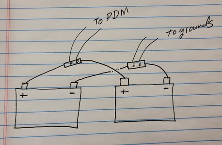
I know many of you use the wiring method on the left (see below). I have seen articles that say the diagram on the right pulls power from the batteries more evenly. A third method (not pictured) would be to run a positive and negative line from each battery to a busbar and then connect those busbars to the negative and positive lines on the RV. This third method would be a bit more challenging…..so based on the experience on this forum, am I good just going with the option on the right? And would this be implemented in two groups of 4?

Opinions welcome.

5064E953-47A1-4BFC-A297-04B75DB76C3E.jpeg
 
Without a busbar, the option on the right is the best way to wire a battery bank of any type.
 
Thanks. Is it worth the effort to even pursue the busbar design? Would it make much of a difference vs the design on the right?

As a follow up question, what gauge of wire would be used in each scenario (2 or 3).

Thanks
Rich
 
I've not seen the option on the right before. What makes it better than the one on the left?
 
the one on the left is supposed to use all cells, as it forces the electrons to enter and exit at far points. Think of how a home water heater works. Cold water enters bottom, and hot water exits the top (or vice versa--not sure really)

Some one much smarter than I am has suggested that it doesn't work like water flow, and somehow the battery at the end outputs much more energy. So the cells that are in parallel need to be drawn from equally. The ones in series will flow like water, as they are increasing the voltage.
 
Interesting as I was just looking at my chassis batteries and kicking around adding a third battery. This attached drawing is on my London Aire with a Freightliner chassis where the 2 batteries are connected with a built in buss bar in the middle of the cables. I would have thought they would have been connected like pic 1 above but both my batteries are feeding the buss bar so the output, (in my mind anyway) is equal and power not passing from one through the other.
 

Attachments

  • Battery.jpg
    Battery.jpg
    877.8 KB · Views: 25
So the cells that are in parallel need to be drawn from equally.
If that is the case, and I have no reason to dispute your findings, wouldn't a setup like this allow for perfectly even draw? Assuming that all the cables were also exactly the same length?

battery.png


Edit: Scottramer must have posted about the same time I was drawing this. His picture appears to be pretty much the same as my diagram.

 
Yes! This is what I was describing as my third scenario…. Having the Neg and Pos connected to bus bars.

I agree this is optimal, but is it worth the extra effort to do this with eight batteries?
 
I plan on doing the bus bar with my lithium conversion.
 

Latest resources

Back
Top