Welcome to RVForums.com

  • Register now and join the discussion
  • Friendliest RV Community on the web
  • Modern site for PC's, Phones, Tablets - no 3rd party apps required
  • Ask questions, help others, review campgrounds
  • Get the most out of the RV Lifestyle
  • Invite everyone to RVForums.com and let's have fun
  • Commercial/Vendors welcome

Welcome to RVForums.com

  • Register now and join the discussion
  • Modern secure site, no 3rd party apps required
  • Invite your friends and let's have fun
  • Commercial/Vendors welcome
  • Friendliest RV community on the web

Notsotalltexan

RVF Supporter
Joined
Mar 21, 2023
Messages
106
Location
San Antonio, TX
RV Year
2025
RV Make
Forest River
RV Model
Forester
RV Length
25
Chassis
Mercedes-Benz VS30
Engine
6 Cylinder Mercedes Diesel
TOW/TOAD
2021 Jeep Wrangler Sahara Unlimited, Blue Ox, Demco Air Force One
Fulltimer
No
Greetings One and All--

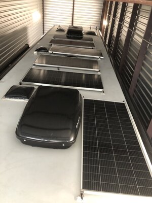
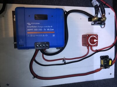
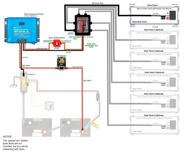
Yesterday I completed installation of six 200W Rich Solar panels on the roof of my Ventana 3709 with combiner box. I also called Mangum Energy to ask whether my 2812 inverter and my new ME-ARC50 remote control advanced series works with my inverter revision or if I needed a software update. I spoke with Scott Buckhouse in tech support and after he determined that I had just what I needed for my new LifeBlue lithium batteries, he walked me through the new settings necessary on my remote then had me crawl into the basement where my Mangum 2812 inverter was mounted and directed me to the reset button just above the green blinking LED. Then he had me hold it down until I saw the lite blinking rapidly and voila, my inverter and remote were now set for lithium batteries, charge controller and solar array.

Scott also told me to be sure and disconnect the positive inverter cable first from the battery and when reconnecting my inverter cables to the Lithium batteries, to connect the negative first, then the positive.

Today I will finish in the basement, replacing the FLA batteries with my two 200Ah Lifeblue batteries, build cables then fire it all up!

Here is Scott's contact info for anyone needing their tech support:

Scott Buckhouse

Product Support Technical Specialist

Magnum Energy, a product brand of Sensata Technologies, 5775 W Old Shakopee Rd Ste 100, Bloomington, Minnesota 55437

[email protected] // 800-553-6418 office // www.sensatapower.com
 
I’d like to see pics of your panel placement if convenient.
 
Scott also told me to be sure and disconnect the positive inverter cable first from the battery and when reconnecting my inverter
Anyone know if this is the propersequence for all invertrs?
 
Anyone know if this is the propersequence for all invertrs?
This is only for magnums as far as I know…as if you disconnect the negative first, it will search for alternative ground (in particular with the BMK installed). It could burn out the BMK…

So they tell me. :)
 
Here are my six roof panels and my controller with breakers and Victron smart shunt. My LifeBlue batteries are Bluetooth too. I should have taken a picture of the two batteries and my master battery disconnect with positive and negative J-Posts. I will and post in a few days.

Thank you to all here who gave me help and encouragement.

Laurent
 

Attachments

  • IMG_0858.JPEG
    IMG_0858.JPEG
    693.9 KB · Views: 35
  • IMG_0863.JPEG
    IMG_0863.JPEG
    613.3 KB · Views: 36
Great news!

One question: It is hard to tell from the pic, but make sure ALL negative connections need to go to the Shunt. The idea is to allow the shunt to see ALL activity between the batteries and all connections, including general 12v, solar and the inverter.
 
Thank you Rich. I specifically asked Jack Caruso with AMSolar this and his reply went as follows:

So just to summarize, the shunt will have 3 wires total connected to it. One on the battery side from the most negative battery connection, and 2 on the load side. One is for the J-post, and the other is for the chassis ground.

This is all I have connected to the shunt, just as he explained.

Laurent
Rich--

Jack also sent me this wiring diagram which was a big help. It is a Victron diagram using the same size charge controller I purchased.
 

Attachments

  • 99-VT085.jpg
    99-VT085.jpg
    81.2 KB · Views: 18
Thank you for noticing this Rich. I think that in my haste, I neglected to run a cable from the J-Post to the load side of the shunt.
 
Ok. And when you say “J Post”, do you mean a Busbar?
 
I asked him about that too. He said in my situation, a junction post does the same thing and would suffice. If I know now what I did not know then, I would have requested busbars. Although, the 3/8" posts were 1.25" long and the nuts had a flange only so I did have room for all the lugs on the J-Posts.

On my two battery posts, the 8M - 20 1" bolts came with a lock washer and flat washer which only left about a half inch of threads available. So with cables built with big lugs for 4/0 cable they sold me and Newmar's 3/0 cable lugs and finally the Victron heat sensor connector eyelet on the positive post, I could not start the bolt. So off to Home Depot I went. They had exactly what I needed but I should have gotten two sets since the same thing happened on the negative battery post.

I lost a few hours of sleep last night wondering how I could have missed the cable from the negative junction post to the load side of the shunt. I'll need to make the access point larger between the battery bank compartment to the control board for that 4/0 cable. To do this I'll use a multi-tool. You probably know the wall of the battery compartment has thin metal on 3/4" plywood. I cut access from the control board side and the multitool goes right through the metal with no effort.

I'll post pictures of both compartments today.

Laurent
 
Ok. So is the J Post just a bolt to consolidate the cables? I had not heard that term before…
 
Ok. So is the J Post just a bolt to consolidate the cables? I had not heard that term before…
Your not alone. Why they economize with terms is beyond me. What ever happened to saying or printing the word, rather than making a conversation out of, oh I mean junction post.

Sorry about the rant!

I use bonding posts all the time. I prefer them over bus bars.
 
I’m back here at the RV storage to add a short 4/0 from the Junction Post to load side of the shunt. Right now I have only a 4/0 from the battery connected to the battery side of shunt. As my picture shows I have a 2 gauge from negative battery terminal on charge controller going to load side and chassis ground. I will add a 4/0 from Junction Post to load side.

Here’s my question: Now my J-post has house ground, inverter ground, bi-direction battery isolation cable and I have a 4/0 from negative most battery to the Junction post. Is this last cable incorrect? Maybe this isn’t necessary? Since I already have the negative most terminal attached to the shunt battery side and then adding the jumper from Junction post to shunt load side?
 
It’s hard to say from your description. Bottom line: battery ground to one side of shunt…. ALL negavite cables to through other side of shunt. As an example, see how I did it with a bus bar. The cable that disappears into the wall is the ground.

072BCE96-8993-45CC-9310-65D0B3DF9039.jpeg
 
Okay thank you!! I will remove that negative battery cable to Junction post. I’ll add new 4/0 jumper to load side from Junction post which is my bus bar.
 
Okay thank you!! I will remove that negative battery cable to Junction post. I’ll add new 4/0 jumper to load side from Junction post which is my bus bar.
Hey Rich--

I've finished all my solar roof and basement installations and yesterday removed and replaced the battery isolator. I had to add wire to the orange ignition wire as it was a tad too short.

Thanks again for your help.

Laurent
 

Attachments

  • IMG_0869.JPEG
    IMG_0869.JPEG
    995.1 KB · Views: 20
Great! Glad your project is moving towards completion. I am happy to be have been able to help as I would like to pay it forward for everyone who has helped me.

Rich
 

Latest resources

Back
Top