Welcome to RVForums.com

  • Register now and join the discussion
  • Friendliest RV Community on the web
  • Modern site for PC's, Phones, Tablets - no 3rd party apps required
  • Ask questions, help others, review campgrounds
  • Get the most out of the RV Lifestyle
  • Invite everyone to RVForums.com and let's have fun
  • Commercial/Vendors welcome

Question Autoformer static voltage

Welcome to RVForums.com

  • Register now and join the discussion
  • Modern secure site, no 3rd party apps required
  • Invite your friends and let's have fun
  • Commercial/Vendors welcome
  • Friendliest RV community on the web

Joe Hogan

RVF Supporter
Joined
Nov 3, 2019
Messages
3,125
Location
Florida
RV Year
2024
RV Make
Newmar
RV Model
Dutch Star 4311
RV Length
43
Chassis
Spartan
Engine
Cummins
TOW/TOAD
2018 Ford Flex
Fulltimer
No
Using the Autoformer the standing or static voltage runs high in my opinion.
Typically find voltages between 130 and 129 with little load, generally.
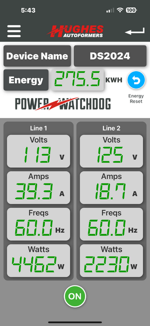
With load the voltages can vary significantly between line 1 & 2. Loaded line as low as 113 and lightly loaded line 130 or 132 cut off.
This has become a nuisance.

Thoughts?
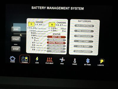

IMG_1749.jpeg
IMG_1725.pngIMG_1725.png
 
It should only boost about 2% when voltage is normal. Is your unit boosting more than that under normal circumstances?
 
what are the voltages when autoformer is removed?
 
~120 volts generally..

Per the brochure the 10% boost should happen only below 113 volts. See below?

“The unit will automatically start boosting 10% if the voltage drops to 113 or below. If the incoming voltage is 115 V or higher, you will have only a 2% boost.”
 
I am wondering if you are getting 125-127 from power company. We see that often in Montana during summers when they boost the line voltage
 
Thank you for that information. Maybe…
 
one thing to note, at least on the silverleaf equipped units like out 16LA the voltage/current sensing device is far from accurate. They used a 559CPF by HMI Systems LLC, it's no longer made and not adjustable.
This was their response when I asked about the differences between the meter reding at the panel tight after the sensor.

Surprising that it would report the wrong voltage since that is a simple measurement and doesn’t require much calibration. It does depend on the wires getting connected correctly. It is expecting to see 110V between L1 and Neutral and 110V between L2 and Neutral. It also measures the frequency on L1 and should report whether it is in phase or out of phase with L2.
The current uses a hall effect sensor which does require calibration but after factory calibration should read within +/- 1 to 2 amps. The current measurement is made by passing the wire through the appropriate hole in the 559CPF. If more than one wire is passed through it will interfere with the measurement.

Most common issues were improper wiring or during installation erasing the factory calibration inadvertently.

The values are then broadcast out to the RV-C CAN bus which have to be decoded by whatever GUI or display is looking for them.
 
Thank you for that information. Maybe…
You can also test the pedestal on the 30amp or 15amp outlets if they exist. This will give you a reference voltage to compare the watchdog with, and allow you to do so without unplugging your coach.
 

Latest resources

Back
Top