Got to spend a pretty good amount of time with the coach this weekend. Pretty sure I got the battery cable issues fixed.
I decided the generator cable goes to the starting batteries. Here's why, That cable not only feeds the generator starter, but also feeds the electrical panel for the turn signals and other things associated with the chassis. Everything works now. Alternator charges as it is supposed to. Will charge both banks of batteries. Generator will do the same when it is running by itself.
I nearly gave up looking to see which cable went to the inverter. Finally did give up as a inverter was a option on my coach. It does not have one.
For the AC's, Microwave, or frig to run (on elec), generator has to be running or plugged into shore power.
Do I really need a inverter? Maybe to have ac's or frig to run off ac while moving. Or leave generator running? Thoughts? How big of a inverter if I do add one. I saw where the new Entegra has 2 - 3000 watt inverters.
I have to replace all of the clearance light front and rear. 20 years of sunlight has turned them a brittle as potato chips.
Got all new leds on the way.
Led licenses plate lights installed also.
The power steps would not stay shut when you closed the door. They would retract and reopen in a few seconds. I figured it had to be the magnetic switch in the door, but could not find it. So I took a chance and used a magnet in a flash light and went around the door frame. BOOM! the steps closed, and stayed closed. What I thought covered a screw was the switch. The cover on the door was the magnet. I popped it out, cleaned 20 years of crap off it, sealed it on the back side with silicone, and made a small hole on the outside and put a thin layer of silicone over that hole. Less resistance for the switch to see the magnet. I am going to replace the magnet.
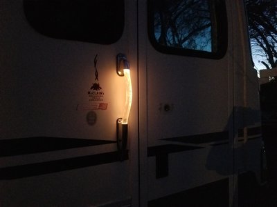
Newmar sent me a "build sheet" that listed a lighted entry handle. Didn't work. Took it off and the bulb socket was shot. Stole a socket off a 68 Nova parts car I have and wired it in. Now it lights up. Pretty cool!
Fixed a latch rod on the engine compartment door.
Gas gauge doesn't work..Mice chewed the wires into by the sender. I can see it, but can't get to it. I was going to cut a hole above it, but that would be in the floor of the living area.
May still do that if I replace the carpet with tile.. Newmar welded brace under the tank when they built the subfloor structure, so I can't drop the tank very easy.
Side note, if you were under the coach without the jacks deployed, or a jack failed and were under the frame, ..you would not survive. I have had 2 cars fall on me and am VERY lucky to be here today. Plenty of room in the middle of the frame rails, but I'm not very comfortable crawling in and out under the frame.
Microwave plate and racks are missing..Those things are outrageously expensive!
Have a handle for the frig coming, lock broken.
Have to fix the vent fan in kitchen that don't work.
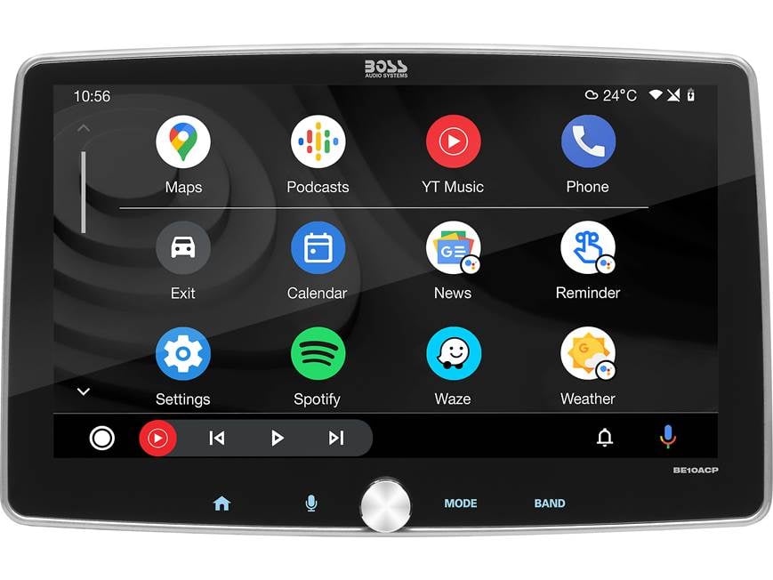
Radio is shot, so I am going to replace it with a BOSS Elite BE10ACP touch pad. It will fit in my stock radio opening and give me the ability to more or less have my phone scene on a 10" monitor on the dash. With a adapter, I can hook up 3 or 4 cameras to it also. Put some new technology in a old bus.
Digital multimedia receiver (does not play discs)

www.crutchfield.com
Dash ac compressor is inop, so I have to figure that out.. Good thing I own a NAPA store!
Change all the filters and oil.
SOMEHOW figure out how to buy tires, and it will be road worthy and everything working.
Besides tires, and possibly kinda pricey ac parts, I really have put much in this coach.
HOPE nothing ugly pops up!
OH 1 more thing, I plan on painting the entire coach. Thinking Black with gold and burnt orange stripes.
But get all the mechanical stuff out of the way 1st.
I have bored ya'll enough, so Good night.
")


