Welcome to RVForums.com

  • Register now and join the discussion
  • Friendliest RV Community on the web
  • Modern site for PC's, Phones, Tablets - no 3rd party apps required
  • Ask questions, help others, review campgrounds
  • Get the most out of the RV Lifestyle
  • Invite everyone to RVForums.com and let's have fun
  • Commercial/Vendors welcome

Need to activate 50 amp

Welcome to our community

  • Register now and join the discussion
  • Modern secure site, no 3rd party apps required
  • Invite your friends and let's have fun
  • Commercial/Vendors welcome
  • Friendliest RV community on the web
I've also have concerns about how all this has been wired. Before this Michigan rv mechanic put in the 30 amp magna inverter my shore power was 50 amp and worked just fine.
 
These panels cannot actually detect amp capability. Our panel, as an example, makes the assumption that of you have 240v potential across Leg 1 and Leg 2...you are plugged into a 50A outlet. If the potential across L1 and L2 is Zero...then you have used a dogbone adapter which ties the L1 and L2 from the coach together...going to a single line on a 30A outlet.

I would see what the logic is for your display panel.
I looked into the display panel and notice three wires that went into a prewired circuit board that controlled what power source was displayed. No obvious dog bone connection. Took three pictures of whatni uncovered.
 

Attachments

  • IMG_20201105_110326709.jpg
    IMG_20201105_110326709.jpg
    2.9 MB · Views: 18
  • IMG_20201105_105651895.jpg
    IMG_20201105_105651895.jpg
    2 MB · Views: 19
  • IMG_20201105_105630199.jpg
    IMG_20201105_105630199.jpg
    2.4 MB · Views: 19

page three has the logic that a similar intellitec panel uses to decide between 50A and 30A.

This manual also has wiring, pinouts, etc...

The dogbone is an accessory device used at the shore power connection. It has a 3-pin TT30 plug to plug into a 30amp shore power receptacle...the other end has a 14-50R 4-pin receptacle to plug your coaches 50A cord plug into. The way they construct the dog bone divides the single Line service of a 30A receptacle...and conducts this to your coaches L1 and L2 leads.
 
Last edited:
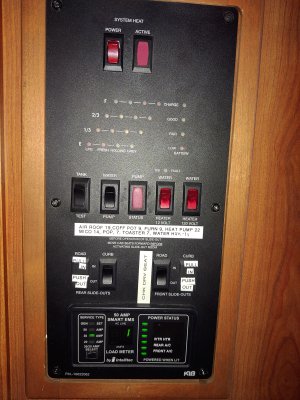
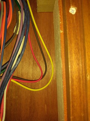
Im not sure of what this power box is for (see two pictures)! On the left the power strip has a 4 ga positive wire coming out of the battery house switch, powered by battery bank. This is currently connected on power strip into lug identified '30 amp system heater'. Just above that lug there is an empty lug labled '50 amp converter'. To the right of that open lug a 6 g wire, connected to the right bus is going back in the inverter area. Question, should the wire connected on the left bus be moved up and connected to the open 50 amp lug?
Not really. The big wire from the battery could be connected to any of those lugs. They share that power thru the copper bar that connects them all.
 
It appears the Model 760 is an upgrade kit...


We need to make sure we get the correct manual for your EMS. They appear to have used multiple different board and connector combinations. Please make sure the schematic that a manual provides Jives with your panel. It wouldn't be fun to troubleshoot, if the wires aren't what they are supposed to be.

Look carefully for part numbers, model numbers on your component boards. Hopefully, we can find the correct manuals on the intellitec website.


UPDATE>>>. THIS looks more like your panel...


IN which case...the connector you are investigating is NOT J4...It is J6. A 5-pin connector... Terminal 1 and Terminal 3 are the L2 and L1 signal respectively...
 

Latest resources

Back
Top Bottom