JeffAndPam
RVF Regular
- Joined
- Jun 26, 2023
- Messages
- 52
- Location
- Alabama
- RV Year
- 2005
- RV Make
- Fleetwood
- RV Model
- Flair, 34R
- RV Length
- 34'
- Fulltimer
- No
Here are my existing house batteries, which have a monster wire running between them:

I'd like to install the following two components between these two batteries: A disconnect switch, and a meter:
(This would go in the space in the lower right)


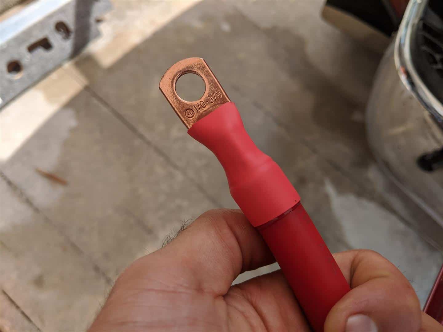
The current wire running between these is pretty thick.
Would I be ok running two 2 awg, or 4 arg wires between them?
Something like: https://www.amazon.com/ABIGAIL-Battery-Inverter-Automotive-Motorcycle/dp/B0BV9TYY5D/?tag=rvf01-20
I'd like to install the following two components between these two batteries: A disconnect switch, and a meter:
(This would go in the space in the lower right)
The current wire running between these is pretty thick.
Would I be ok running two 2 awg, or 4 arg wires between them?
Something like: https://www.amazon.com/ABIGAIL-Battery-Inverter-Automotive-Motorcycle/dp/B0BV9TYY5D/?tag=rvf01-20