Welcome to RVForums.com

  • Register now and join the discussion
  • Friendliest RV Community on the web
  • Modern site for PC's, Phones, Tablets - no 3rd party apps required
  • Ask questions, help others, review campgrounds
  • Get the most out of the RV Lifestyle
  • Invite everyone to RVForums.com and let's have fun
  • Commercial/Vendors welcome

FYI Generator AGS tested successfully

Welcome to RVForums.com

  • Register now and join the discussion
  • Modern secure site, no 3rd party apps required
  • Invite your friends and let's have fun
  • Commercial/Vendors welcome
  • Friendliest RV community on the web
Some Victron inverters have power assist like mine so if the loads are higher than the grid can supply then the batteries augment.
 
2 inverters only make my point even clearer. This means both L1 and l2 have 30amp potential and 15amps anywhere else will trip the breaker.

Joe, this is where you should test. And also make sure that you are wired to L1 and L2. If both inverters are pulling on a single line then you will trip without any other loads.

You have a max of 45amp on each line, and continuous load of 80% of 45amp.

Remember this is a 10kva, so it can only provide 43amp surge and 80%continuous per line, and a total of 83 amp at sea level.

The 10Kw can easily get overloaded if not balanced.

66amps continuous rating is the standard, although I have run them at 70amp continuous with no issue.

A load for 10 minutes above 70amp could trip the breaker. A single line load over 35 amp could trip breaker.
 
Keep in mind it’s a 45A 2-pole breaker.
 
Keep in mind it’s a 45A 2-pole breaker.
Of course. L1 and L2.

It also a max load of 10000volt amps

10000/120=83amps
83 * 80% =66.6amps

66/2=33amps for L1 and 33 amps for L2

This shows how you can easily overload that generator with 2 inverters and even the smallest of extra loads like a refrigerator, air, television, etc.

I would turn the inverter to 20amp when using generator.

You do have the ability to exceed the 80% recommendation, but then you are dealing with unknowns and require plenty of monitoring and testing to know what limits to expect.

Altitude, temperature and humidity all factor in to what available power can be drawn from the generator, so exceeding 80% comes with unknown results.
 
The moral here is know how to manage your loads. I'm staying with 30A on my inverters unless I have a problem. The first 22A I'll give up is OASIS electric elements and go burner only. If I need more power for loads I can easily turn off the charger from my phone through VRM or Bluetooth but putting the inverters in inverter only mode instead of ON.

Using 50A for input current in each inverter if on GEN will trip the breaker as I learned and people need to understand what these settings do and what the limits are of the grid (shore/gen).
 
Reading the posts and references to 2 pole breakers. So a 45 amp breaker, is that at 240 volts? Or 45 amps on each 120 volt leg? In other words either Leg 1 or Leg 2 is limited to 45amp? This starts to makes sense. 10kW at 240v is 42 amps. 42 amps on each leg. Leave some room for spikes and you get to a nice round 45 amp breaker.
Possibly I am missReading this?
 
If you where to take power across L1 andL2 you would in fact see 240V, if the phases where out of phase.

In generators this is not guaranteed, and the power delivery of the Onan RV models is such that both kegs are in phase, and prevents you from actually getting 240v.

Instead what is created is 2 legs of 120V , with the combined rating equaling the generators specs.

The breaker is sized at 45amp, but the generator cannot make that much power for long. The breaker tripping means the generator became overloaded.
 
I just looked at the specs and it appears the onan 10Kw can in fact deliver 240v. I have seen some that do not, but that may be the 7500 and below.
 
You have a max of 45amp on each line, and continuous load of 80% of 45amp.
To clarify @redbarons point - in electrical circuit design you never design a circuit to be loaded no more than 80% of the breaker rating. Breaker design allows +/- 10% trip variability of the rated amperage amperage when new. If the breaker is tired, it may trip earlier. For example, a 20 amp breaker is allowed to trip anywhere between 18 and 22 amps. When hooked to 50 amp shore power, I set both of my Victron inverters to 40 amps max input. A couple of times, I have been in an old park where I have had to drop that all the way to 30 amps to keep from tripping the breaker.
 
Let's take a step back. Many of us, self included (guilty as charged) have Magnum on the brain. @Joe Hogan has Victron as do I. Modern inverters such as Victron are "smart" inverters and adjust charge rates, etc. as needed. The term "max charge rate" is a Magnum term, that is not present in Victron. Victron's inverter has you enter the shore current limit - i.e. what is the size of your input you're connected to. If connected to a 50A pedestal, this can be set to 50A, if GEN (for me) then 30A, if connected to a 120V/15A plug then 15A. It has nothing to do with charge rate. There is no setting for such that I can find via the Cerbo GX, I'd have to check the BMS, etc. via Bluetooth to see more settings available.

From the Victron manual, the charge rate is taken from the surplus after the loads are met:

PowerControl – maximum use of limited shore current The MultiPlus can supply a huge charging current. This implies heavy loading of the shore connection or generator set. Therefore a maximum current can be set. The MultiPlus then takes other power users into account, and only uses 'surplus' current for charging purposes.

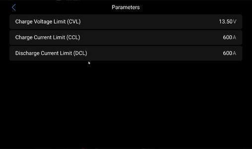
The parameters screenshot below is not settable, it's per the BMS as limits per type of battery. It doesn't mean this is a max charge rate or anything of the like of Magnum.

As to running on GEN the Cerbo GX new UI has great info and can show you the watts in, watts out, etc. You can look at the detail of supply and demand easily. Also VRM has numerous charts you can use and learn how it works and manages the loads, charging, etc.

Cerbo GX firmware 3.54 as of this posting:
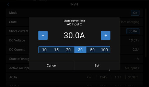
shore-current-limit.jpg
params.jpg
 
Let's take a step back. Many of us, self included (guilty as charged) have Magnum on the brain. @Joe Hogan has Victron as do I. Modern inverters such as Victron are "smart" inverters and adjust charge rates, etc. as needed. The term "max charge rate" is a Magnum term, that is not present in Victron. Victron's inverter has you enter the shore current limit - i.e. what is the size of your input you're connected to. If connected to a 50A pedestal, this can be set to 50A, if GEN (for me) then 30A, if connected to a 120V/15A plug then 15A. It has nothing to do with charge rate. There is no setting for such that I can find via the Cerbo GX, I'd have to check the BMS, etc. via Bluetooth to see more settings available.

From the Victron manual, the charge rate is taken from the surplus after the loads are met:


The parameters screenshot below is not settable, it's per the BMS as limits per type of battery. It doesn't mean this is a max charge rate or anything of the like of Magnum.

As to running on GEN the Cerbo GX new UI has great info and can show you the watts in, watts out, etc. You can look at the detail of supply and demand easily. Also VRM has numerous charts you can use and learn how it works and manages the loads, charging, etc.

Cerbo GX firmware 3.54 as of this posting:
View attachment 27126
View attachment 27125
Neal - You are missing a key point. Nothing being discussed cares about the brand of charger, but not having a Magnum puts you at a disadvantage unless you are taking data from the EMS and responding to the commands designed by EMS to manage the voltage.

Your victron is only as smart as the data it has. Victron does not monitor any other loads. According to the documentation, the line rate limit is how the max rate is set. This is identical to magnum, and only the wording is different. If you set to 30AMP line, it will consume 30amps during a bulk charge. The instructions are very clear that you should set this low enough to allow of other devices.

With a charge rate of 30 amp, and ignoring all the other consumers of power, you are taking 30amp from L1. If you have a 2nd charger, and its installed properly, then it will take power from L2.

When being stored, or only using 12v appliances, you can safely operate at 30 amp and never have a problem. Having any other power consumed from the power will also take power from L1+L2. The EMS job is to adjust the charge rate as part of charger before it shunts power on other devices. It will shunt power, but the timing can sometimes be too slow.

There are other power sources that do not have the ability to shunt. The refrigerator, outlets in the RV, etc.

With a 10KVA, loads of 8amps can be enough to trip the breaker. With a 7500KVa generator, 31.25 is the max amps.

You feel comfortable with your setup, and I am certainly not telling you how to run your coach. I am just explaining the science behind the settings and educating others on how this works. @Joe Hogan may benefit from some of this knowledge. If not, feel free to scroll on. I just enjoy the topic and do this daily in my work when designing rack power loads for datacenters. That environment is very different from RV, as guessing is forbidden, and even a 1amp out of spec is reason to fail an audit.

If I owned a Victron, I would set it to a max rate of 20amp for daily use on 50amp, and 5 amp for anything less. That is just me, not a recommendation for others.
 
@Joe Hogan before this dialog started you made a change on your inverter to 30A. What was it set to prior to this change?

Next time you’re at your coach set both inverters to 10A and tell me what your EMS shows and can you run one or more air conditioners?

My coach is always 50A as the batteries will power anything but I’m not sure how yours is setup. My EMS is still in play and always shows 50A unless I change it.
 
My Victron Inverters apparently have been set to 30 amps. We discussed this, 50A vs 30A, etc., when we picked up the RV from Newmar. Apparently I did not remember what we had decided but looks like we left it at 30A.
We were lucky enough to have KIB onsite at CPU to discuss the system as our particular setup was new to Newmar for this model year.
The advice I have come across with other Techs has varied probably because my setup is relatively new to Newmar techs.
I've relied on onsite KIB Techs to answer questions when I find them. We went through the setup again at the International this past summer in Pueblo CO as KIB techs were present.
Still working on understanding all the ins and outs of the power system. Early on had issues with the Battery Isolation Solenoid. Newmar swapped that part out at the Tampa show a couple of years ago.
When the batteries are depleted is when most issues arise. Still debating Solar with myself.

Our previously owned CanyonStar with 1.7 kW of solar panels and a 800 amp LiFePo4 battery bank rarely suffered with power issues, surprisingly.
 
I don’t think I was a part of that discussion at your FPU as I had 50A set on mine which I learned was wrong per my GEN breaker issue. It’s a continuous experimenting and learning. I think SES did your install. Mine is unique as well.

As to VRM I’m not sure if you looked at it much but a few items of note:
  • You can set alarm rules to get notified on events
  • You can invite others to view your setup as some are watching mine. SES has admin control so they go in when I need help
  • There’s an app for your phone. It’s just a mobile web view.
  • You can do firmware updates but be careful as updating the inverter is involved and requires separate software for the config files. Updating the other stuff is simple.
Looking forward to what you learn.
 
When I get back in the coach again I’m going to experiment with the different settings and try 50A when on shore power as I had set for months and see if there are any issues. Plan is to hopefully set 50A on shore and 30A when on GEN and see what happens. I’m also going to reach out to SES to discuss again. I had this discussion at completion of my install and left unclear. They set it to 50A.
 
@Neal - You may have a unique setup, if your coach is wired to run all loads off the inverters. That would mean that the transfer switch is directly connected to the inverters and not to the interior power panel. I am not sure if that is what you meant, but if you did in fact setup with L1 going to to inverter1, and L2 to inverter 2, then your main panel being fed from Inverter1/Inverter2, this would change everything, as you would match the shore power connection for the inverters.

This is very different than how newmar wires the RV stock, but does resemble how Datacenter are connected, with all power always coming from the UPS/Inverter setup, and the inverters are either in bypass mode (Shore to Equipment) or ONLINE mode, where the power is cleaned and delivered with batteries always online.

Your setup is great, and is the future of how RV's should be designed, but is very unique (meaning most don't have this elaborate design)
 
Yes, it is custom and designed to be a 50A coach on battery with new heavier gauge wires from inverters to breaker panel to safely run AC’s, option to bypass inverters, solar integrated, power assist, on and on. I worked with SES to do it right the first time and it’s plumbed to double the battery bank if I choose. My setup is discussed on the site in detail.

I don’t know what Newmar is doing such as in the case of Joe. I think SES told me they are doing the installs for Newmar for lithium coaches. I could be wrong. I don’t know Joe’s setup in detail but I saw it when there at his FPU.

What I’m trying to do is figure out a way to simply test a setup hence the idea of let’s put the inverters in 10A input and see what the system does and limits.
 
Not sure on your design, and I will look at the write up. For the datacenters, we will match the input amp as you said, so 50A makes sense when you have shore power. Your generator would require 30A setup, and when connecting to shore power, you will have to lower it to 10A if you are connected to a 20A circuit, since L1+L2 are combined, and your inverters are taking the power based on L1 & L2. If you have a smaller circuit (15A) then you will need to set to 5A.

Like I said, the design you have is ideal for a always on connection. It is also the easiest to retrofit. The advantage of this setup is the wiring already exists in the electrical bay.

I would install it this way on my LADP if I was going to go the lithium battery route.
 

Latest resources

Back
Top