We really need to know your wiring architecture. For example...my coach is 50A and uses a 30A input to the inverter (MS2812)
Shore power cord (50A) >>>>>> 50A surge protector >>>> transfer switch.
Generator >>>>>>>>transfer switch.
Transfer switch takes one (generator priority) >>>>>>>>Precision Circuits Load Center.
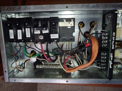
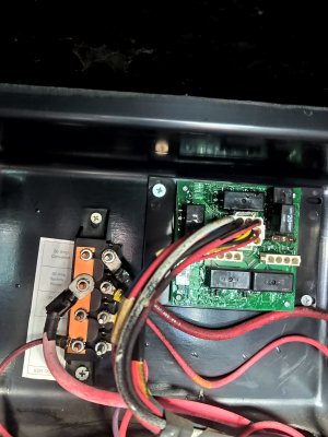
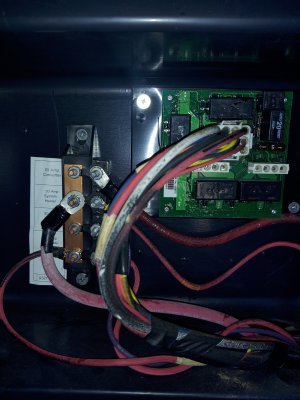
Precision Circuits load center is divided into two buses...a MAIN...and an Inverter.
The main bus gets it’s input from the transfer switch and is protected by a pair of 50A breakers. The main bus has branch breakers for air conditioners, washer, dryer, water heater element, block heater, and a 30A branch supplying the MS2812 Inverter.
Output from the inverter comes back to the panel and feeds the Inverter bus thru a 30A breaker. The smaller Inverter bus has branch circuits for kitchen outlets, residential fridge, microwave, entertainment system outlets, etc...
Using the Inverter you have now...the above architecture should work. The power cord, and transfer switch wiring will have to be upgraded to #6 (50A ampacity) vs #10 (30A ampacity).