Welcome to RVForums.com

  • Register now and join the discussion
  • Friendliest RV Community on the web
  • Modern site for PC's, Phones, Tablets - no 3rd party apps required
  • Ask questions, help others, review campgrounds
  • Get the most out of the RV Lifestyle
  • Invite everyone to RVForums.com and let's have fun
  • Commercial/Vendors welcome

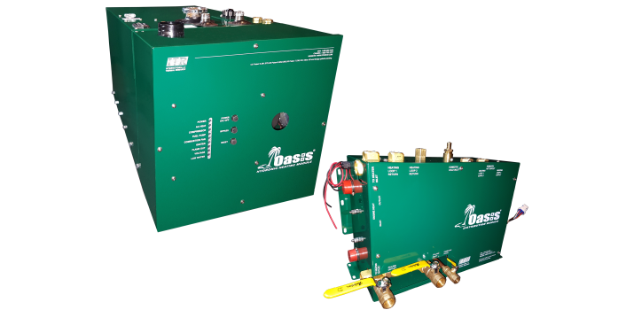
How To Verify your ITR OASIS Two Electric Burners are working

Welcome to RVForums.com

  • Register now and join the discussion
  • Modern secure site, no 3rd party apps required
  • Invite your friends and let's have fun
  • Commercial/Vendors welcome
  • Friendliest RV community on the web

Neal

Staff member
RVF Administrator
Joined
Jul 27, 2019
Messages
13,028
Location
Midlothian, VA
RV Year
2017
RV Make
Newmar
RV Model
Ventana 4037
RV Length
40' 10"
Chassis
Freightliner XCR
Engine
Cummins 400 HP
TOW/TOAD
2017 Chevy Colorado
Fulltimer
No
In my other thread about AC Heat not working I had a short, a second electrical short in the wiring of my OASIS system. In verifying the wiring ITR Heat had me go to my EMS panel and then turn AC I on and check for an AMP change. I showed +12 AMPS. Then switch to AC I and II and you should see a gain of 12 AMPS on both L1 and 12 AMPS on L2. L2 was NOT showing any change for me. I verified all wiring, wire nuts, etc. and could not figure out the issue. I then removed and reinserted the spade connectors in the 3rd back relay which is related to AC II and now it works. I'm sure I'll now enjoy much better heating via electric than before. This could have been this way since taking delivery and never knowing it so the above steps may help you verify for your own peace of mind that your AC I and AC I/II are working as it should.
 
Last edited:
Neal,
I just checked mine. Believe it or not, I have the same problem. AC1-13A, AC1+AC2 -13A.
On our trip last week, I noticed it was taking longer than usual to heat the water. Always something.....
 
Just checked mine AC1 increase 12a L2, AC1/2 increase 10A L1, thanks for the info
 
In my other thread about AC Heat not working I had a short, a second electrical short in the wiring of my OASIS system. In verifying the wiring ITR Heat had me go to my EMS panel and then turn AC I on and check for an AMP change. I showed +12 AMPS. Then switch to AC I and II and you should see a gain of 12 AMPS on both L1 and 12 AMPS on L2. L2 was NOT showing any change for me. I verified all wiring, wire nuts, etc. and could not figure out the issue. I then removed and reinserted the spade connectors in the 3rd back relay which is related to AC II and now it works. I'm sure I'll now enjoy much better heating via electric than before. This could have been this way since taking delivery and never knowing it so the above steps may help you verify for your own peace of mind that your AC I and AC I/II are working as it should.
@Neal … where is this relay located?? Down by the Oasis unit or at the control panel over the drivers seat? Did you get a picture?

FLSteve
 
There are 3 relays on the bottom left of the oasis. Remove the front panel and you’ll see it on the left. FYI if needed you can remove the front shroud/cover of the oasis unit by loosening 3 screws and lifting it off. Newmar may have installed the floor mounting bolts into this shroud so use a 7/16 socket or ratchet wrench to remove the two bolts if needed. It’s a good exercise in learning to access the oasis internals which is not hard and helps for a good wiring inspection. I used a voltage pen to test the 120V power and without that today I’d been lost.
 
If your AC Heat green light is not coming on run a faucet on hot water for 1 minute and then do your test.
 
Today I did some troubleshooting. Opened up the Oasis, and could not find anything wrong.
Got back to the display panel, and noticed with the switch to AC1/AC2, Line1 is 122V/12A draw, and Line2 is 7V 1A ???

Line status.jpeg


Checked the transfer switch, both lines are hot. Inside the coach the AC breaker panel, the main double 50A breaker raised my suspicion.
When I touch L1 breaker with the tester, it is buzzing strong. When I touch the L2 side, nothing.
Opened the panel, and both lines coming to the breaker are hot. so I'm suspecting the L2 side breaker is bad.
It is Eeaton brand, but I'm not sure if it is anything special about it?
The fun will continue tomorrow, and hopefully I will not electrocute myself ?
 
Look carefully at the breaker model number. The shore power and inverter breakers are different. You need the exact correct model number.

The test in this thread requires 50A service otherwise GEN power. Not 30A service.
 
I have a good 50A service at our home RV garage. Tomorrow will remove the breaker and try to match the part number at Lowe’s or H Depot.
 
I’m stumped.
Today I opened the main panel and checked all leads with wolf meter. Both L1 and L2 are getting 120V.
But on the Power Control Monitor, I’m getting L2 7V like the picture I posed yesterday.
Turned off the shore power and fired up the generator. No change. L1 shows 7V. Any ideas?
 
The test in this thread requires 50A service otherwise GEN power. Not 30A service.
Explain please. Why wouldn't this test still show a second amperage increase on a 30A service when AC2 is activated?

TJ
 
Last edited:
@TJ&LadyDi I tested mine on 30a service and worked. I think you need to be aware that if nearing 30a overall load you could have a load shed situation which could affect your reading.
 
@TJ&LadyDi I tested mine on 30a service and worked. I think you need to be aware that if nearing 30a overall load you could have a load shed situation which could affect your reading.
That makes sense, @NWIP; the test, itself, should work UNLESS you pull enough power to exceed 30A and cause a load shed. Thanks, Bill.

TJ
 
Explain please. Why wouldn't this test still show a second amperage increase on a 30A service when AC2 is activated?

I believe when you are on 30A you are only using one line of L1 and L2. 50A is 2 x 30A lines, no? When I was on the phone with ITR they told me that it had to be 50 and I assume because of this. I believe too that when you're on 30A you can ONLY use AC I and NOT AC I/II.
 
I’m stumped.
Today I opened the main panel and checked all leads with wolf meter. Both L1 and L2 are getting 120V.
But on the Power Control Monitor, I’m getting L2 7V like the picture I posed yesterday.
Turned off the shore power and fired up the generator. No change. L1 shows 7V. Any ideas?

@Buly I think this warrants a new thread on the topic of your problem. I suggest using the salesman switch to kill 12V power to reset your EMS but again maybe a new thread to focus on this problem.
 
I believe when you are on 30A you are only using one line of L1 and L2. 50A is 2 x 30A lines, no? When I was on the phone with ITR they told me that it had to be 50 and I assume because of this. I believe too that when you're on 30A you can ONLY use AC I and NOT AC I/II.
Hmmmm. I have a 30A service here at the sticks-and-bricks that I have the MADP plugged into currently and I am able to use both AC1 and AC2 on it. At least, both indicator lights are on and it keeps the coach as warm as I think it should with both elements on. We are plugged in using a 50A-to-30A adapter that splits the power to each leg (L1 & L2). I wonder if that makes a difference?

TJ
 
In my coach for example you can put the switch to AC I/II but only one leg exists on 30A service. @Chuggs maybe you can chime in? The green light will come on but it doesn't mean you have both heating elements in use. I really don't know how the 30A works between L1 and L2. Maybe something manages which path the trons take. Thinking about how Air Conditioners on the roof handle this, I don't think everything is on just one line so I'm stumped.
 
Just checked mine AC1 increase 12a L2, AC1/2 increase 10A L1, these were my results on 30A service. I had an increase of amperage L2 when selecting AC1 and increase of amperage on L1 when selecting AC1/2 which I am assuming is really just turning on the second heating element.

My understanding of Oasis AC heating elements is 1 element provides approximately 5000 BTUs and other element 10,000 BTUs for 15000 BTUs with both active. I would of thought that amperage draw would be slightly different between the 2 elements but saw 10a increase for each.

Just trying to understand the system and now starting to question what I thought I knew?‍♂️
 
My understanding heating elements are 5000 BTU each (net 10K BTU when using AC I/II). The burner is 50K BTU.
 

Latest posts

Latest resources

Back
Top